
This is my latest project that I have made up and built with components around an Arduino Mini Pro.
This summer I picked up an Arduino Uno start-kit and a friend came up with an idea of making a display showing the time when the underground is leaving. I got excited and got a bit carried away with the task as I like displays a lot.
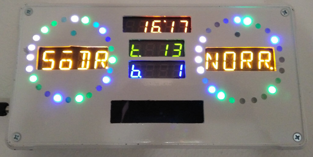
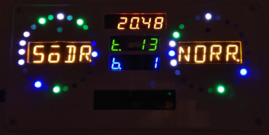
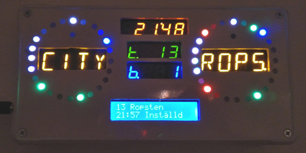
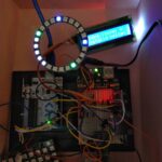
The basic function of the Timetable Display is to show when the underground/bus will be departing from the station updated in real time. There are 24 LED:s showing the number of minutes to departure (i.e. 0 – 23 minutes). The left circle shows the minutes for south going services and the right circle shows the minutes for north going services.
-
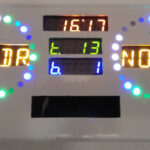
- Front with time
-
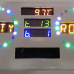
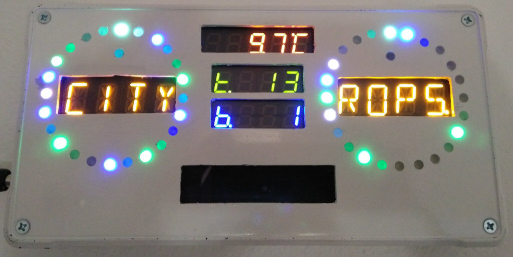
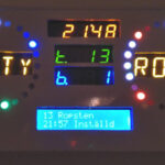
- Front with temp
-
- Front with time in darkness
-
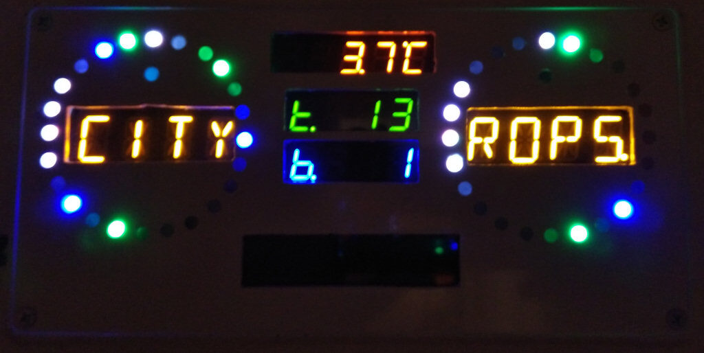
- Front with temp in darkness
-
- Front with cancellation
-
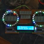
- Testing circles and LCD
-
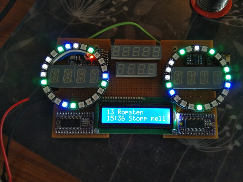
- POC in progress
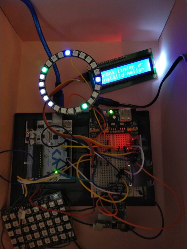
The green LED:s are one service (e.g. underground number 13 in the pictures) and the blue LED:s are another service (e.g. bus number 1). If there are delays the new departure time is showed instead as and alternated with a purple color LED in the circle. If the service is cancelled the departure time is alternated with a red color LED in the circle.
Also any delays or cancellations will be written out in clear text on the LCD at the bottom of the unit to make it easy to understand what the cause is for the delay or cancellation.
The display is updated every 15 seconds using a WIFI connection. It features a “blank mode” showing no data when no information has been received in the last 3 retries to prevent showing stale data.
Timetable Display technical features
Because of the limited amount of RAM (32kB prg, 2kB data) in the Arduino I decided to develop a small server program running on a separate server as well that does all the handling of the data I receive from the TrafikLAB:s API:s. Then a very small and specific data is sent to the Arduino for each request.
- Data requests sent over WIFI at 15 seconds intervals.
- Display current time and outdoor temperature alternatively.
- Displaying up to 20 unique arrival times in minutes using circle LED:s for two traffic lines (blue resp. green LED:s) in a circle for each direction.
- Displaying the actual traffic number for blue resp. green LED:s. (remotely configurable)
- Displaying two alternating texts in each circle. (remotely configurable)
- Indicating delayed service in the circle LED:s by alternating purple circle LED.
- Indicating cancelled service in the circle LED:s by alternating red circle LED.
- Indicating arrived service by flashing circle LED:s with bright colour (blue resp. green LED:s).
- Multiple services with the same arrival time but with different service numbers in the same direction will be displayed alternatively in the circle LED.
- Multiple services with the same arrival time and the same service number in the same direction will be stacked after each other.
- Indicating optimal time to leave zone in each white circle LED:s. (remotely configurable)
- Indicating zero minutes using white circle LED. (remotely configurable)
- Indicating arrival times in the optimal time to leave zone and zero minutes by alternating white and blue resp. green LED colours.
- Adjusting the brightness of all LED’s according to surrounding lights using an LDR sensor.
- Information about cancelled or delayed services in clear text on backlit LCD, displayed alternatively as 6 blocks of 16×2 characters.
- LCD backlight is turned off when no information is displayed on the LCD.
- Red LED indicator flashing when failed to receive data.
- Display shutdown when data was not properly received in 3 consecutive requests to prevent display of stale traffic information.
- Configuration request sent when the unit is starting.
- Reset-command can be sent to reset the unit remotely, e.g. when configuration changed.
- Micro switches for activating programming and LED-testing modes.
Components used in this project
The display was built on a prototype board by soldering break-out versions of the components for simplicity. The following components were used in this project:
- 1 pcs Arduino Mini Pro
- 2 pcs Holtek HT16K33 16×8 I2C LED drivers
- 4 pcs 2×14 segment Yellow LED-displays
- 5 pcs 7 segment Orange LED-displays
- 4 pcs 7 segment Green LED-displays
- 4 pcs 7 segment Blue LED-displays
- 2 pcs LED rings with 24 addressable WS2812B LEDs
- 1 pcs 16×2 character back-lit LCD
- 1 pcs PCF8574 I2C interface for LCD
- 1 pcs ESP8266 ESP-01 WIFI Transceiver Wireless Module
- 1 pcs 5V to 3.3V level converter
- 1 pcs LDR sensor
- 2 pcs micro switches
- 1 pcs prototype board
- 1 pcs 5V power adapter
Recent Comments